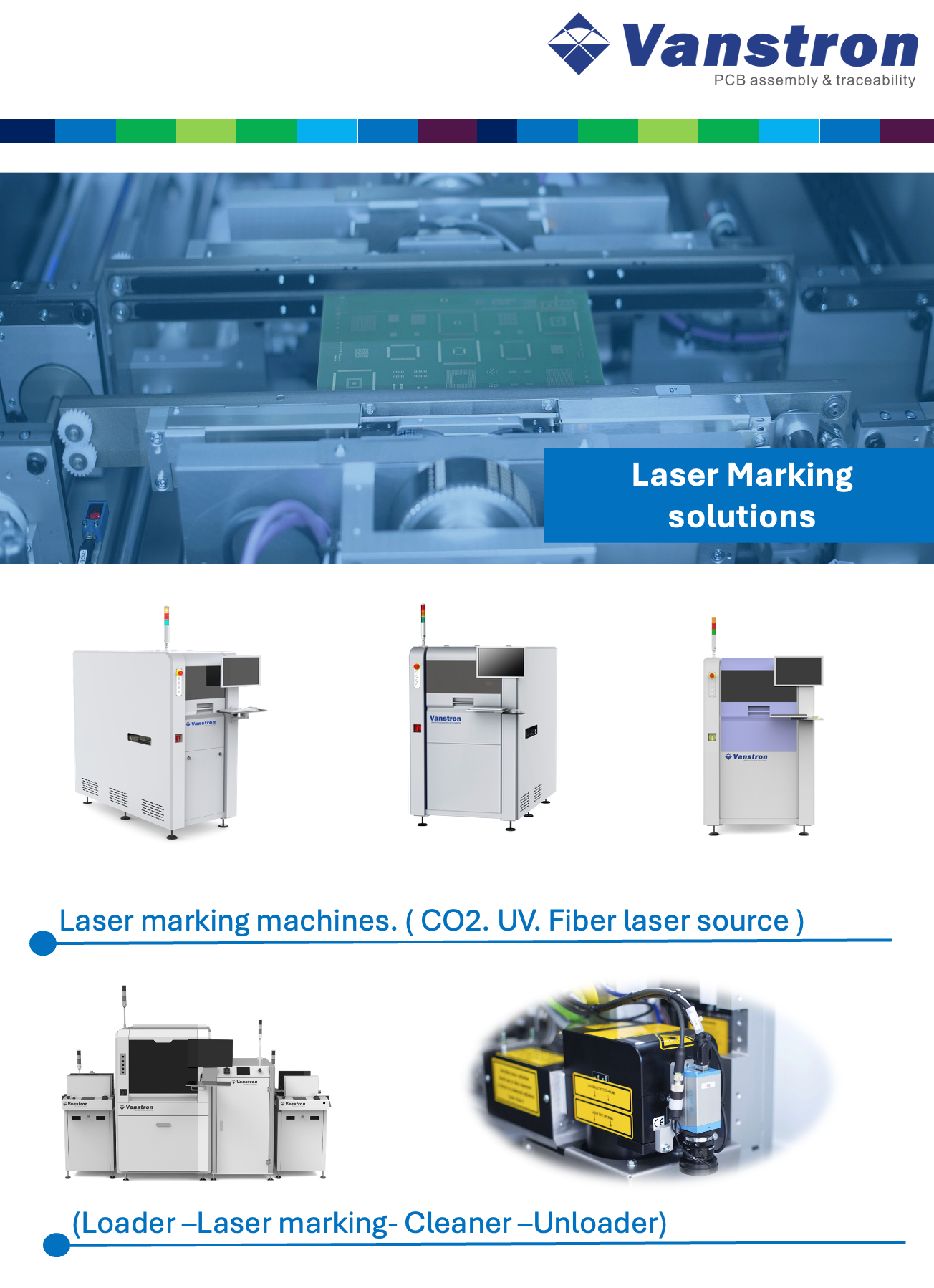
Advantages of Pseudo-Coaxial Vision in PCB Laser Marking
Here is a summary of the advantages of using Pseudo-Coaxial Vision (often referred to in this context as Through-the-Lens or TTL vision, or Coaxial Vision via a beam combiner) compared to Off-Axis (Side-Axis) Vision for inline laser marking of QR codes on PCBs.
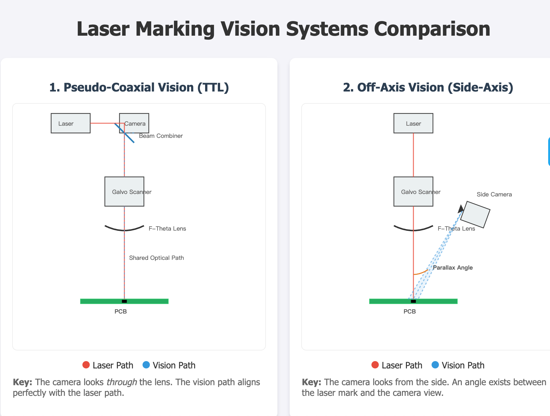
Pseudo-Coaxial Vision
(Off-Axis (Side-Axis) Vision)
1. Superior Calibration and Alignment Accuracy
• Direct Optical Path: In a pseudo-coaxial system, the vision camera shares the same optical path (usually via a dichroic mirror or beam combiner) as the laser beam. This means the camera "sees" exactly what the laser "sees."
• Elimination of Parallax Error: Off-axis cameras view the target from an angle. If the PCB height changes (warpage) or the Z-axis focus shifts, the position of the mark in the camera's view shifts relative to the actual laser position. Pseudo-coaxial vision eliminates this parallax error, ensuring the laser marks exactly where the vision system targets, regardless of slight height variations.
2. Compact and Simplified Mechanical Design
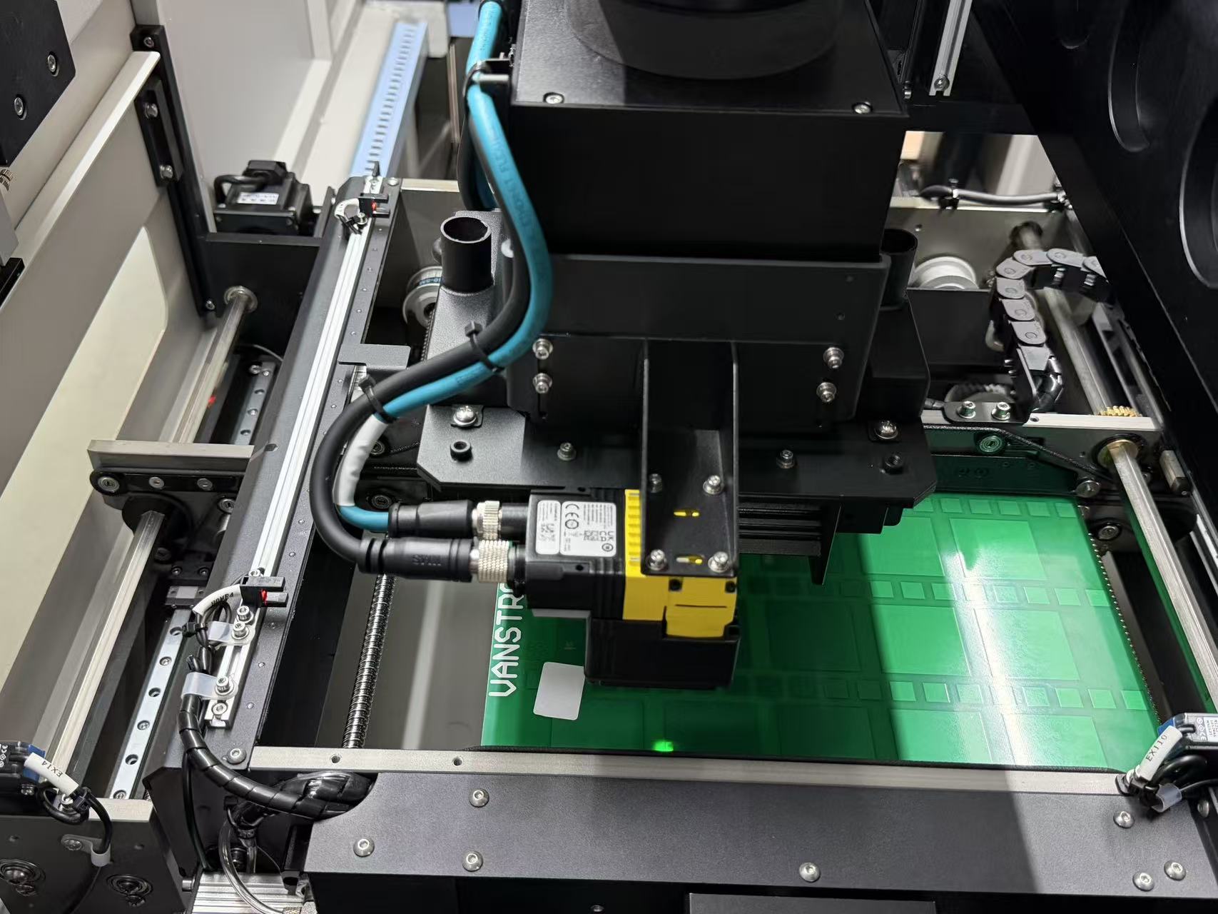
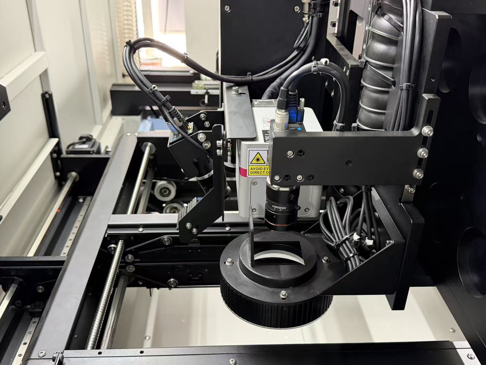
• Space Efficiency: Inline PCB handling equipment often has limited space. A pseudo-coaxial setup integrates the camera directly into the galvanometer scanning head or the laser optical path. This removes the need for bulky external camera brackets and lighting fixtures hanging off the side of the laser head.
• Reduced Interference: There is no risk of an external camera physically colliding with components on the PCB or the conveyor mechanism.
3. Real-Time "What You See Is What You Mark" (WYSIWYM)
• Pre-Marking Simulation: You can overlay the marking template directly onto the live video feed with extremely high precision. This makes setup and recipe creation much more intuitive for operators.
• Post-Marking Verification: Because the camera looks through the scan lens (F-theta lens), it can immediately verify the mark quality and position without moving the galvanometer or the PCB to a separate inspection station.
4. Robustness Against PCB Warpage and Positioning Errors
• Auto-Focus Compatibility: If the system is equipped with a 3D dynamic focus unit, a coaxial camera can assist in determining the focal plane more accurately than an angled camera, which struggles with depth perception.
• Distortion Correction: Off-axis cameras require complex software calibration to correct the trapezoidal distortion caused by the viewing angle. Coaxial vision views the field (mostly) perpendicularly, reducing perspective distortion and simplifying the image processing algorithms required for reading high-density Data Matrix (ECC200) codes.
5. High-Precision Mark Placement on Small Components
• Field of View (FOV) Alignment: For high-density PCBs where QR codes must be placed on very small areas (e.g., shielding cans or specific fiducials) without damaging surrounding components, the absolute coordinate synchronization provided by coaxial vision is superior. Off-axis systems are more prone to "drift" over time due to thermal expansion or mechanical vibration affecting the separate camera mount.
Summary Table
Feature | Pseudo-Coaxial Vision (TTL) | Off-Axis Vision (Side-Axis) |
Parallax Error | None (High accuracy at varying heights) | High (Sensitive to Z-height changes) |
Calibration | Simple (1-point or 9-point, highly stable) | Complex (Requires frequent coordinate mapping) |
Space Requirement | Compact (Integrated inside optics) | Bulky (Requires external mounting) |
Perspective Distortion | Low (Top-down view) | High (Trapezoidal view requires correction) |
Precision | High (Ideal for high-density PCBs) | Medium (Acceptable for large clear areas) |
Conclusion:
For the PCB traceability industry, where precision, space constraints, and handling PCB warpage are critical, Pseudo-Coaxial Vision is the superior choice. It ensures that the Data Matrix code is marked exactly where intended and can be verified immediately, maximizing the First Pass Yield (FPY) of the production line.